


Peeling back the layers
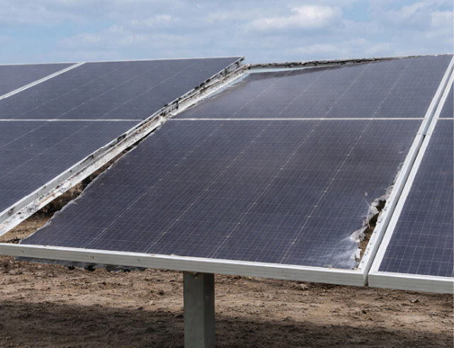
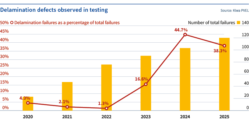
Poor material choices, reduced usage of encapsulants (thinner and/or slimmer), inadequate lamination methods, and process controls can all play a role, leading to rising failure rates. The proportion of delamination failures has climbed from a low of just 1.3% for PQP tested bills of materials (BOMs) produced in 2022 to 44.7% and 38.3% for BOMs produced in 2024 and 2025, respectively (see chart, page 53). This alarming trend has continued in 2026.
One-third of delamination defects came after damp heat (DH) testing (1,000 hours or 2,000 hours exposed to 85 C, 85% relative humidity), but delamination failures were also observed during initial characterizations and after thermal cycling (TC), mechanical stress sequence (MSS), potential induced degradation (PID), and ultraviolet induced degradation (UVID) tests.
Field failures
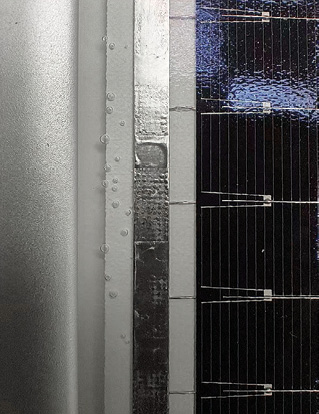
Multiple BOMs from a wide range of module manufacturers exhibited delamination and/or bubbles at the module perimeter. This is considered a major defect when those bubbles or delamination reduce electrical creepage distances to less than the minimum specified in the IEC 61730 safety qualification standard.
There have been multiple occurrences of severe field delamination over the last few years. Unfortunately, some have shown how delamination at the module perimeter can create serious arcing and fire risks. In a recent example from Kiwa PI Berlin (see photo p.54), insufficient creepage distance resulted in electrical arcing and subsequent fire failure. Bubbles at the glass edge of a module compromised the UL/IEC 61730 required creepage distance of 10.4 mm for a 1,500 V module and formed a conductive path between the internal electrical circuit and the frame, resulting in significant electrical arc faulting.
Delamination defects
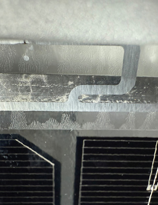
Delamination or bubbles occupy their own, separate categories as significant defects. Bubbles are air or gas occlusions in the continuity of a material from the module laminate (e.g., encapsulant). They are usually circular or roughly oval shapes, with limited sizes (a few millimeters). Delamination is the separation of two materials forming the module laminate (e.g., encapsulant-to-glass interface), which is usually randomly shaped and can cover large areas.
These defects can be further defined based on their location: short module edge, long module edge, corner, junction box, or over the cells. Bubbles are mainly observed above the active circuit and at the module edge, whereas delamination is most often observed at the module corners and edges.
Potential root causes
Encapsulant base resin has a notable impact on delamination occurrences. Using EPE (a polyolefin layer sandwiched between two layers of ethylene vinyl acetate) as the front and rear encapsulant triggers the greatest number of major delamination defects. More than 30% of the 42 BOMs using EPE experienced a major defect. The encapsulant scheme with the second-highest major defect rate was polyolefin (POE) on the front and rear sides, resulting in 20% of 15 BOMs experiencing a major defect. BOMs with front-side ethylene vinyl acetate (EVA) exhibited the fewest major failures, although that was also the least commonly used front-side encapsulant over the past three years of PQP testing.
Despite these general trends regarding the base resin, Kiwa PVEL has found that encapsulant manufacturer and model do not seem to be strong factors in the presence of delamination. In many cases, the same encapsulant model was used across multiple module manufacturers/BOMs, with a range of results – including no delamination, minor delamination, and major delamination.
Counterintuitively, a thinner encapsulant does not necessarily mean a higher risk of delamination. Kiwa PVEL analyzed delamination failure rates against area weight for the EPE encapsulant subset. While these failures were mainly observed after DH, TC, MSS (due to its inclusion of humidity freeze) and PID testing, there was no obvious correlation of major delamination failures with encapsulant thickness. The highest prevalence of major defects used front encapsulant with an area weight of 480 g/m2 across the range of submitted BOMs from 380 g/m2 to 530 g/m2. However, we did note that tests with high temperature (around 85 C) and high humidity (85% relative humidity) exacerbated the risk of delamination.
As production workshops have strived to reduce costs and optimize labor usage over the past few years, material usage has been progressively reduced. In the case of encapsulant, this happened by downsizing the material dimensions. We investigated the occurrences of delamination failures at the module corners against the delta between encapsulant and glass widths. The highest failure rate (18.6%) was observed for the most aggressive encapsulant width (with an encapsulant width at least 6 mm less than the glass width), indicating that the use of narrower encapsulant presents a higher sealing risk at the module corners.
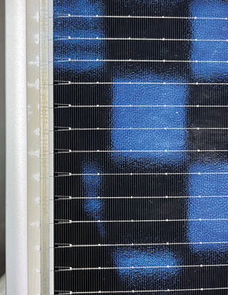
Lamination method and process are also important. During the lamination process, the module stack is pressed together under high temperature and pressure, driving the encapsulant to melt and cross-link, binding the laminate together. During this step, the encapsulant tends to spread out along the edges and corners, and manufacturers use a variety of techniques to limit this and avoid edge pinches, i.e., reduced encapsulant thickness around the module perimeter.
Historically, stiff locking frames around the laminate perimeter were commonly used during glass-glass module lamination, along with additional strips of encapsulant at the edges. Currently many module manufacturers are attempting to use simple alternatives to accelerate throughput, such as using tapes along the edge or only around the laminate corners to collect the encapsulant overflow. Test results show that the various alternatives to locking frames all result in higher rates of delamination failures, with corner-only taping methods appearing the most susceptible to delamination.
Regarding the lamination recipe, we did not observe obvious correlation between the failures and the lamination process controls with regards to temperature or lamination times. Most tested BOMs had lamination temperatures primarily concentrated between 140 C and 155 C, while lamination time mostly fell within 400 to 750 seconds, none of which appeared unusual. Major defects were densely clustered in this zone of lamination temperatures and times, implying that other factors, such as material quality or equipment stability, may be the main drivers.
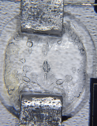
The use of some fluxes resulted in a specific delamination failure type: bubbles expanding from string busbars at the soldering points. Solder flux is used for soldering cell sub-strings to the top and bottom string busbars. Major defects were observed on several specific solder fluxes: of the 44 flux models tested over the 2024-26 period, major delamination was found only with five flux models. The possible root causes include improper flux recipe and/or residue cleaning.
Impacts and mitigation
Our preliminary conclusions on delamination risk factors are seen in the table on p. 54. These highlight how some causes are more impactful than others. While delamination has many causes, downsizing of encapsulant dimensions, along with simplification in methods used to control encapsulant overflow during lamination, seem to both play a critical role. Other material-related causes, such as the use of improperly qualified solder flux or a new encapsulant recipe, also require continuous quality control and in-production verification.
While no obvious correlations were found with encapsulant area weight and process control (lamination time and temperature), we believe those should also be kept in focus for quality control, as they likely play a role in delamination failure mechanisms.
While it has always been important, the rise in delamination defects is a pressing reminder that the industry must mitigate reliability risks despite ever-present cost pressures. Module manufacturers and their customers need to be aware of these issues and advocate for strict quality controls and process compliance to prevent these defects from reaching the field.
The post Peeling back the layers appeared first on pv magazine Global.
What's Your Reaction?
 Like
0
Like
0
 Dislike
0
Dislike
0
 Love
0
Love
0
 Funny
0
Funny
0
 Wow
0
Wow
0
 Sad
0
Sad
0
 Angry
0
Angry
0













Comments (0)